A Diplexing Junction at C Band
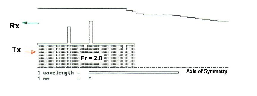
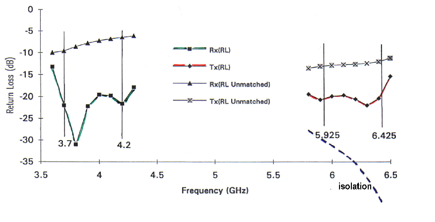
A compact 4/6 GHz coaxial diplexer(Figure 1) was designed using a modal matching program(AXIAL) and was reported in reference[1]. The upper band signal (5.925 to 6.425GHz ) in the form of a dominant TE11 mode is transmitted through the central circular waveguide loaded with PTFE into the common circular waveguide on the right hand side. The lower band signal (3.7-4.2GHz), which is cut-off in the central waveguide, is diplexed into the outer coaxial waveguide from the common circular waveguide. A small number of matching irises are required to improve the return loss performance of the device. By loading the inner waveguide with PTFE, the task of matching the bifuricated junction is made significantly easier. The combination of dielectric loading and use of matching irises in the outer coaxial waveguide also yields a good isolation(coupling between the inner and outer waveguides) performance in the upper band as shown in Figure 2. Henderson & Richards[2] have reported the use of such a diplexing junction in a 4-port C band feed compact enough for front-fed reflector configurations.
1. S. M. Tun, Mode matching analysis of combined circular and coaxial strucures loaded with dielectrics, Computations in Electromagnetics, IEE Conf. Publ. No. 350, Nov 1991, pp. 230-233.
2. R.I. Henderson, P. J. Richards, Compact circlarly-polarised coaxial feed, ICAP 95, IEE Conf. Publ. No.407, April 1995, pp.327-330.