AXIAL
Analysis of Multiple-coaxial Waveguide and Horn Structures
Applications of AXIAL
AXIAL can be used to analyse combined circular and multiple coaxial structures with partial dielectric loading(optional). Such structures can be excited with dominant TE11 or TE21 modes corresponding to a circular or coaxial waveguide input port. In principle, any circularly symmetric structure which can be decomposed into circular and coaxial regions can be modelled (Figure 1) using AXIAL.
The recent addition of TEM mode excitation extends the analysis to complex coaxial connector structures and in-line coaxial filters.
Typical structures (Figure 2) that can be analysed are
- Cassegrainian /splashplate feed reflector
- Circular choked waveguide radiators
- Circular multimode/corrugated horns
- Circular waveguide irises and transitions
- Circular waveguide tapers and transformers
- Coaxial waveguide tapers and transformers
- Coaxial diplexers/orthomode junctions (dual band)
- Coaxial multiband radiators
- Dielectric core loaded/filled circular horns
- Dielectric rod radiatos
- Disc-on--rod radiations
- Ring and cavity-loaded corrugated horns
- Horn with lens
 Figure 1: Sample Circular Cross-Sections which can be implemented in AXIAL Yellow and Orange indicate loading with two sorts of dielectric |
 FIGURE 2: Sample Geometries for AXIAL. Yellow indicates dielectric loading of the structure |
Mathematical Modelling Used in AXIAL
The mathematical basis of the analysis program exploits a modal matching technique. The radiating structure to be analysed must be modelled as a number of discrete cylindrical segments supporting propagating as well as evanescent TE and TM circular or coaxial waveguide modes. For waveguides partially loaded with dielectrics intrinsic hybrid modes of the cross-section are utilised. The modal matching employs a scattering matrix approach to determine the complex coefficients of the modes at the aperture of the structure. The far-field radiation patterns are then obtained by summing individual radiation patterns of TE, TM and hybrid modes at the aperture, weighted by the complex mode coefficients.
The dominant TE11 mode excitation of either a circular or coaxial input waveguide is assumed.
Operation of AXIAL
The program suite AXIAL consists of a number of pre and post processor programs and a mode-matching analysis program AXIAL.
Input data files for AXIAL can be prepared interactively using the pre/post processor which incorporates many screen editing facilities. A waveguide/horn profile generator is also built into the pre-processor to enable repetitive generation of complex structures such as corrugated horns by simply altering a few key parameters. The profile of the resultant structure can be viewed and modified interactively prior to analysis. The computed radiation patterns of the horn can also be displayed on the computer screen and each radiation point can be examined.
A number of small utility programs to generate ring-loaded horn geometries and dielectrically loaded horn profiles are also included in the AXIAL package.
AXIAL was developed by Dr.Soe Min Tun of S.M.T. Consultancies Ltd.
Available Versions
Two versions of AXIAL are available as executables. The full version incorporates dielectrics where multiple layers of dielectrics can be placed inside any of the coaxial and circular waveguide regions. The reduced version assumes uniform air-filled waveguide regions. AXIAL is available on these platforms.
Examples
A typical example is an axisymmetric Cassegrainian reflector with a splashplate feed [1], [2], [3]. The exciting waveguide with its dielectric is modelled as a circular waveguide while the exterior of the waveguide and the reflector are modelled as a coaxial section (Figure 3). The great advantage of this type of analysis is that is allows an optimisation to be carried out which is much more accurate than the usual ray tracing. The result is an ability to design a high efficiency (65%) reflector with sidelobes of -22 dB and low spillover (<-40 dB) when the aperture is relatively small in wavelengths. Examples up to 12 wavelengths have been designed. An example of aperture diameter 5.5 wavelengths is described in [3].
A very low sidelobe Potter horn has been designed and optimised using AXIAL (Figure 4 and Figure 5). AXIAL predicted the peak gain to be 22.55 dBi at 5.255 GHz and this has recently (2004) been measured by NPL, Teddington, UK for QinetiQ, Farnborough, UK to be 22.454 +/-0.05 dBi at 5.255 GHz.
Waveguide components can also be modelled. Figure 6 shows an Ortho Mode Junction to separate RX/TX at C-band.
TEM line structures can also be modelled. Figure 7 shows a compensated coaxial line connector and the corresponding mode-matching results compared against measured and FDTD results.
Here are a splash-plate feed and a co-axial diplexer, designed using AXIAL.
Here is a brief presentation on two systems designed using AXIAL (originally given at ESTEC in October 1997 by Pat Foster)
Platforms
AXIAL is available on these platforms.
References
- S. M. Tun, Mode Matching Analysis of Combined Circular and Coaxial Structures Loaded with Dielectrics. Int. Conf. on Computation in Electromagnetics 91, Nov 1991, IEE Conf. Publ. No. 350, pp 230-233.
- S. M. Tun & P. R. Foster, Mode Matching Analysis of Small Cassegrainian Reflector Antennas, ICAP 93, April 1993, IEE Conf. Publ. No. 370, pp 627-630.
- P R Foster & S M Tun, A Small Splashplate Feed Reflector, ICAP2003, Exeter, UK, 2003, Vol 1, p87-89
FIGURE 3: Cross-section of a Cassegrainian Reflector with splashplate feed
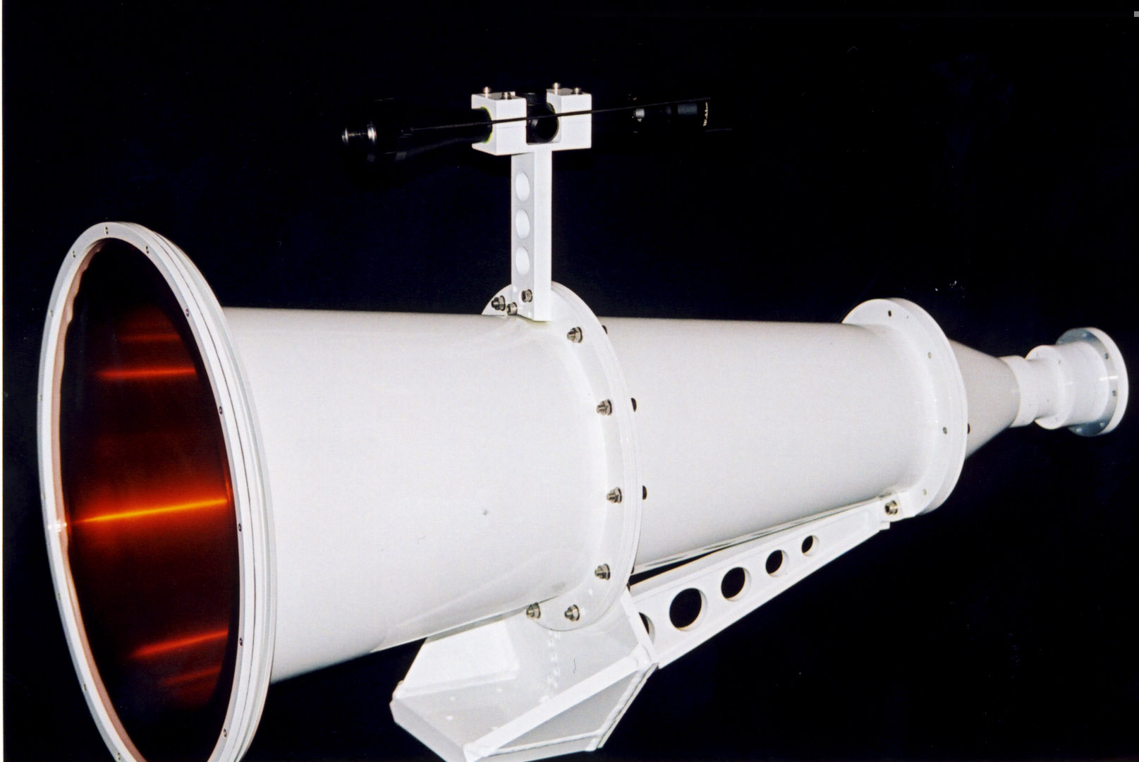
FIGURE 4: Photograph of low sidelobe Potter Horn
 |
 |
FIGURE 5: Comparison of measured and predicted patterns of Low sidelobe Potter Horn together with the template. Left is E-plane. Right is H-plane