REFLECT
Analysis of Multiple Reflector Systems
Applications Of The Program REFLECT
The program REFLECT can be used to analyse single or dual reflector systems. Struts may be included and array feeds may be used. A variety of surfaces is available, including a numerically defined surface
Modelling Methods Used By REFLECT
The mathematical basis of this analysis program is Physical Optics (PO) combined with Physical Theory of Diffraction techniques (PTD) corrections for the reflector and subreflector edge currents. Such a combination has been found to be more robust and accurate than Geometrical Optics (GO) and Geometrical Theory of Diffraction (GTD) when applied to dual reflector systems. Accurate feed models are required and can be incorporated in REFLECT using a variety of techniques, including the use of Spherical Wave Expansions.
In REFLECT, the PO analysis technique is used to compute not just the main beam radiation patterns but also the spillover fields of single or dual reflectors. PTD corrections can improve prediction accuracy when computing low cross-polarisation levels or wide-angle scattered patterns.
Program Contents
The program REFLECT consists of an Executable for WINDOWS NT/2000/XP. The computation requires file input to the program. A pre and post processor has been developed. See the example below which contains screen dumps and graphics of output from the graphics processor.
Facilities are available for several types of reflector and sub-reflector (flat plate, paraboloidal, parabolic cylinder, One-dimensional rotationally symmetric numerical surface, numerical surface on X,Y grid, ellipsoidal or hyperboloidal). Feed models are available for Circular Waveguide Feeds, Rectangular Waveguide Feeds, Spherical Wave Expansion, Gaussian Taper Feed and Arrays of Circular Waveguide, Rectangular Waveguide or Gaussian Taper Feeds. Output can be in the near or far field. Multiple scattering between two surfaces can be included on command.
Struts and multiple ray blockage are included on user-command. Struts are treated using the Induced Field Ratio method (IFR) where Axial and Radial currents are included and can be derived in closed form. Ray blockage including self-blockage by the feed is incorporated.
Validation
A large amount of validation has been carried and REFLECT has been shown to give accurate results when compared to other well-documented reflector programs or to measurement. Some examples are shown below. Figure 1 shows the wide angle pattern of a large offset reflector when calculated by GTD alone and by REFLECT using PO+PTD. Figure 2 compares the patterns from a dual reflector using various techniques. Figure 3 shows a comparison between four methods for predicting the scattered patterns from a hyperboloidal subreflector
Results from REFLECT modelling three reflectors in a quasi-optics system ( a pdf file) have been generated for comparison with other modelling and measurement.
The University of Berne has used REFLECT to model three feeds using in KOSMA and compared the results with measurement.
Example
The geometry of a symmetric reflector with a single strut is displayed in Figure 4 as taken fromthe REFLECT graphical pre-processor. Figure 5 shows a contour plot in spherical format of the radiation from this reflector at 10.7 GHz. Figure 6 shows the same reflector modelled at 10.7 GHz without a strut.
REFLECT was developed by Dr.S.M.Tun of S.M.T. Consultancies Ltd.
Platforms
REFLECT is available on these platforms.
"FIGURE 1: Comparison between GTD(GRASP4) and PTD(REFLECT) for a Single Offset Reflector Antenna.
FIGURE 3:-Predicted Scattered Patterns from a Hyperboloidal Subreflector Illuminated by a Uniform Source.
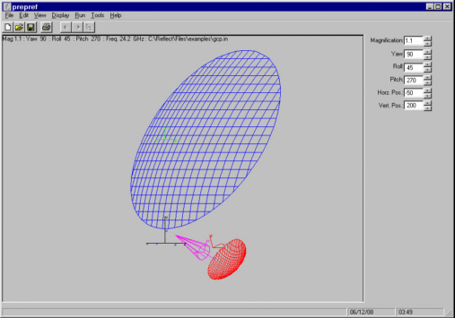
FIGURE 4:- A Dual Offset Reflector Antenna Geometry Viewed inside Pre/post-processor.
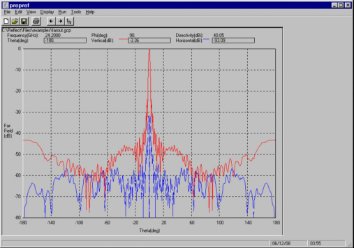
FIGURE 5:- Predicted Patterns for Antenna in Figure 4 Viewed inside Pre/post-processor.
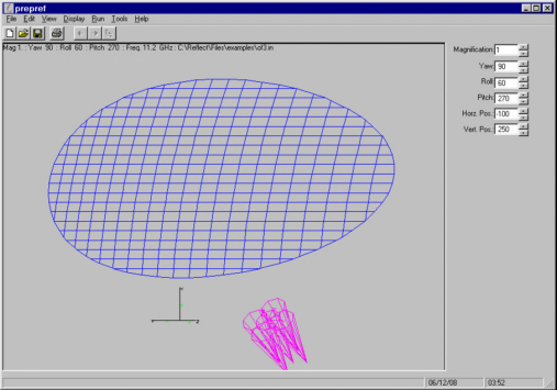
FIGURE 6:- A Single Offset Reflector Antenna Geometry Viewed inside Pre/post-processor.
FIGURE 4 Geometry of symmetric reflector with one strut as shown by the graphical pre-processor.
FIGURE 5 Contour plot of radiation pattern at 10.7 GHz using geometry of Figure 7 - symmetric reflector with one strut.
FIGURE 6 Contour plot of radiation pattern at 10.7 GHz using geometry of Figure 7 without the strut.