OPTRTCC EXAMPLES
Examples of Optimisation of Mixed Rectangular and Circular Structures
Example 1 Waveguide Filter
Example 1 is a low-pass filter of rectangular waveguide. The initial geometry (Figure 1) gives the response in frequency of Figure 2. After optimisation, the geometry was as shown in Figure 3 and the response as in Figure 4. The return loss over the band 10.7 to 12.75 GHz has improved from -24 dB to -40 dB while the level of rejection was maintained at 15 to 14.5 GHz.
Example 2 Circular Horn
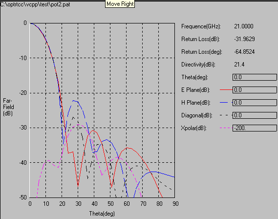
A circular multimode horn of large aperture was required to have a crosspolar level of -30 dB over a 10% bandwidth. The optimisation was carried out by varying the dimensions of the input geometry of the horn. Figure 5 shows the final geometry. Figure 6, Figure 7 and Figure 8 show radiation patterns at 19, 20 and 21 GHz where the peak cross-polarisation over the band is less than -32 dB.
FIGURE 1 Initial Geometry
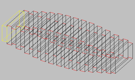
FIGURE 2 Initial Response
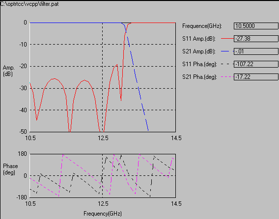
FIGURE 3 Final Geometry
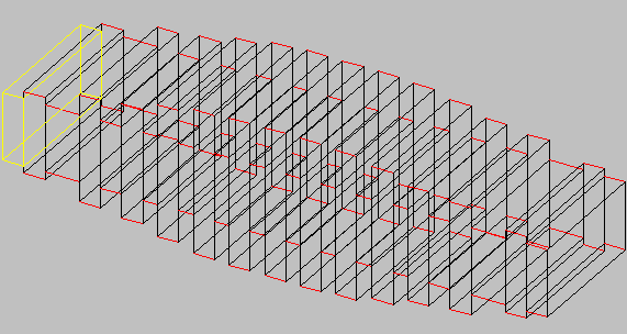
FIGURE 4 Final Response
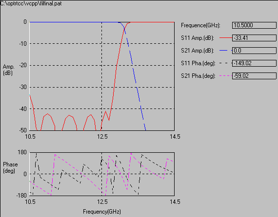
FIGURE 5 Optimised Geometry of Circular Horn
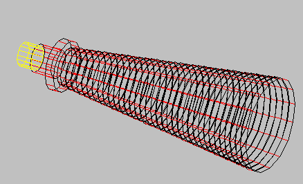
FIGURE 6 Radiation Pattern at 19 GHz
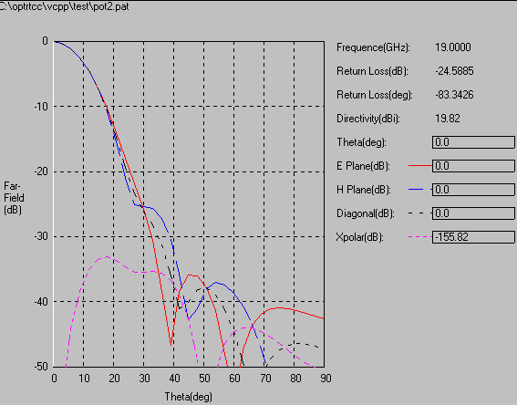
FIGURE 7 Radiation Pattern at 20 GHz
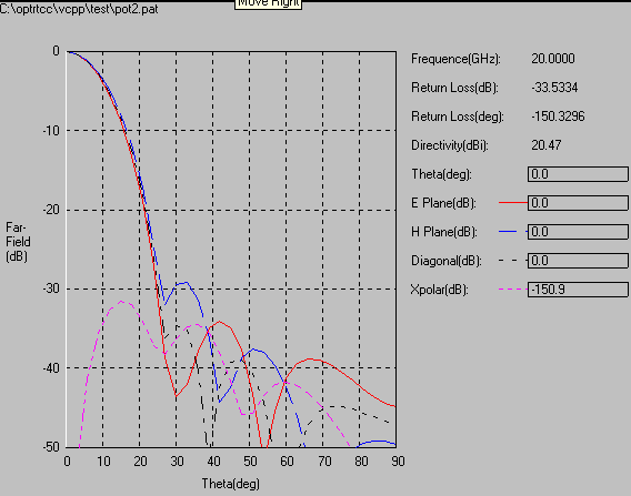
FIGURE 8 Radiation Pattern at 21 GHz